
Coiled tubing
CT Simulator
Draw the well, build the string and the BHA, set the job and read the results. The well and the BHA are kept in this browser, so the editors you used elsewhere on this site open here as they were left.
Plan a coiled tubing job on a large screen
The CT Simulator takes a coiled tubing job from the well to the forces in one workspace. You draw the well, build the CT string and the bottom-hole assembly, set the job, and read the weight indicator, the depth reached before lock-up, the set-down weight, the overpull and where the string starts to buckle. It looks and works like a drawing program: a ribbon of steps, a project palette, a drawing area, a properties palette and a command line.
The five steps
- 1 Well Draw casing, liner, tubing and completion tools on the schematic and add the deviation survey.
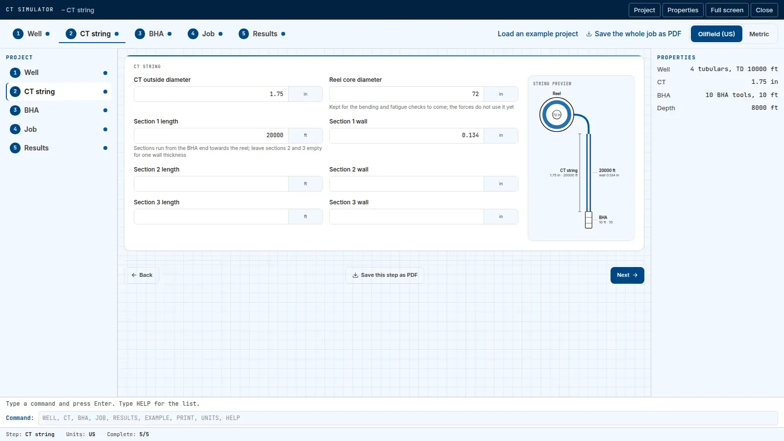
- 2 CT string Set the outside diameter, the wall sections and the reel, and see the string drawn.
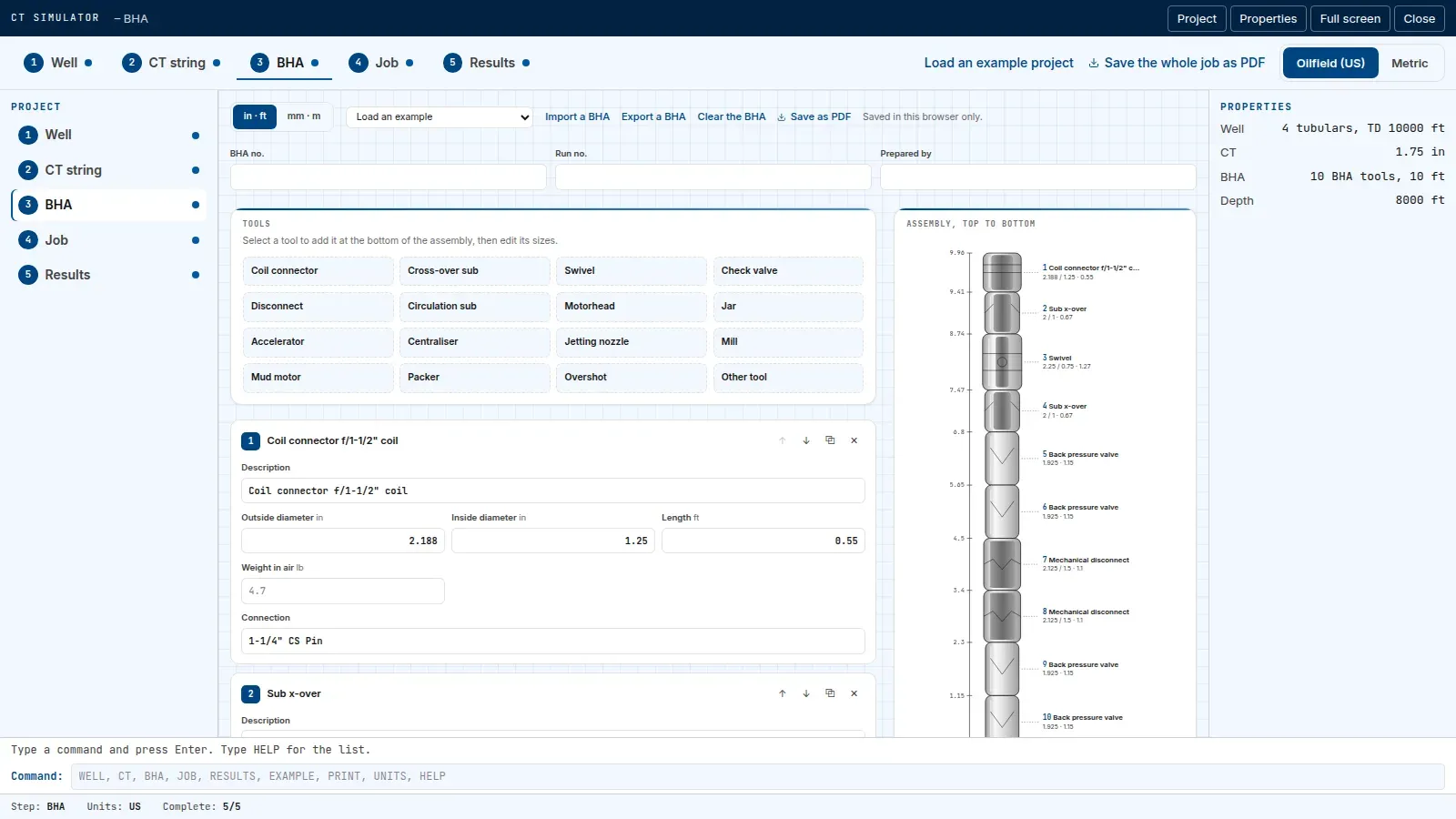
- 3 BHA Build the bottom-hole assembly from tools, with their sizes and weights.
- 4 Job Set the depth, the fluids, the friction and the limits.
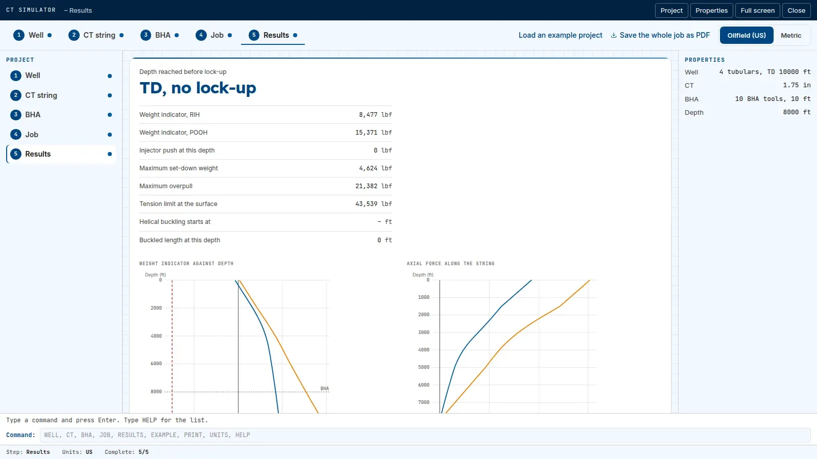
- 5 Results Read the forces and the weight indicator and force charts, and save the job as a PDF.
The workspace opens over the whole screen. Press Esc or Close to come back to this page.
No mobile version. The CT Simulator works only on large screens and tablets, from 768 pixels wide. Open this page on a computer or a tablet.
The well, the BHA and the job are kept in this browser and sent nowhere.
The workspace
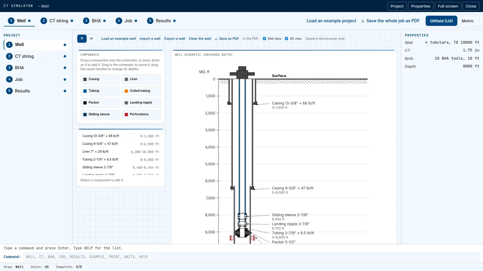
Well schematic (measured depth)
Components
3D well path
No survey yet: the well is drawn straight down to its deepest component.
Colour: dogleg severity, from low to high.
CT string
Kept for the bending and fatigue checks to come; the forces do not use it yet
Sections run from the BHA end towards the reel; leave sections 2 and 3 empty for one wall thickness
Assembly, top to bottom
Fill in these before the results mean anything
Depth reached before lock-up
–
- Weight indicator, RIH
- –
- Weight indicator, POOH
- –
- Injector push at this depth
- –
- Maximum set-down weight
- –
- Maximum overpull
- –
- Tension limit at the surface
- –
- Helical buckling starts at
- –
- Buckled length at this depth
- –
Weight indicator against depth
RIHPOOHLock-up limit
Axial force along the string
RIHPOOHCritical buckling force